What does a wavy line mean in a drawing? Lines in the drawing
Types of lines, their purpose and thickness are established by GOST 2.303-68 (Table 2). The solid thick main line is taken as the original line. Its thickness S should be selected between 0.6 and 1.5 mm. It is selected depending on the size and complexity of the image, format and purpose of the drawing. Based on the thickness of the solid thick main line, the thickness of the remaining lines is selected, provided that for each type of line within one drawing in all images it will be the same.
Table 2
|
Name |
Line thickness in relation to the main line thickness |
Main purpose |
|
1. Solid thick main line |
0.6... 1.5 mm S |
Visible contour lines; visible transition lines; section contour lines (extracted and included in the section) |
|
2. Solid thin |
From S/2 to S/2 |
Contour lines of the superimposed section; dimensional and extension lines; hatch lines; leader lines; shelves of leader lines and underlining labels; lines for depicting boundary details (“settings”); limit lines of extension elements in views, sections and sections; imaginary transition lines (traces of planes, lines for constructing characteristic points for special constructions) |
|
3. Solid wavy |
From S/3 to S/2 |
Break lines; demarcation lines between view and section |
|
4. Line |
From S/3 to S/2 |
Invisible contour lines; invisible transition lines |
|
5. Dash-dotted thin |
From S/3 to S/2 |
Axial and center lines; section lines, which are axes of symmetry for superimposed or offset sections |
|
6. Dash-dotted thickened |
From S/3 to (2/3)S |
Lines indicating surfaces to be heat treated or coated; lines to depict elements located in front of the cutting plane (“superimposed projection”) |
|
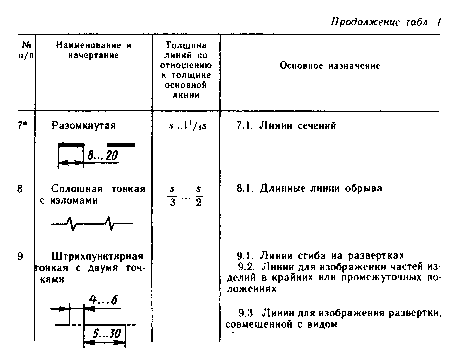
7. Open |
From S to 1.5S |
Lines with broken sections |
|
8. Solid thin |
From S/3 to S/2 |
Long break lines |
|
9. Dash-dotted with two dots thin |
From S/3 to S/2 |
Fold lines on developments; lines for depicting parts of products in extreme or intermediate positions; lines for the scan image combined with the view |
Note.
Line thickness S/3 is allowed only for drawings made in ink, in formats A4 to A2.
In dashed lines, the strokes should be of equal length, and the spaces between them should be the same. The dash-dot lines must intersect and end in dashes. The center lines should extend beyond the outline of the circle by 3...5 mm. For circles with a diameter of 12 mm or less, the center lines are drawn as solid thin lines.
Examples of the use of various types of lines in the drawing are shown in Fig. 5.
Rice. 5 Applications of different types of lines in a drawing
Lines may have a special purpose, for example, to depict threads, boundary slots, zones with different surface roughness, etc. Their use is regulated by special ESKD standards.
The quality of the drawing largely depends on the right choice type of lines, maintaining the same stroke thickness, length of strokes and distance between them, accuracy of their execution.
GOST 2.303-68* (ST SEV 1178-78) establish the outlines and main purposes of lines on the drawings of all industries and construction (Table 1).
The thickness of the solid main line should be 0.5..1.4 mm, depending on the size and complexity of the image, as well as the format of the drawing. The thickness of the lines should be the same for all images in a given drawing, drawn to the same scale. The length of strokes in dashed and dash-dotted lines is selected depending on the size of the image. The strokes in the line and the spaces between them must be the same length.
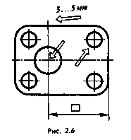
Dash-dotted lines must begin, intersect, and end with dashes. Dashed-dot lines used as center lines are replaced with solid thin lines if the diameter of the circle or the dimensions of other geometric shapes in the image less than 12 mm (Fig. 2.6).
Examples of using lines are shown in Fig. 2.7 and 2.8, a, e. When making educational drawings, it must be taken into account that the ease of use of the drawing and its suitability for reprography (making copies ) and microfilming.
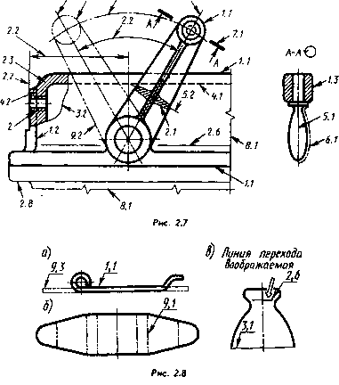
The main lines (lines of the visible contour) should be given a thickness of 0.8...1.0 when tracing, dashed lines (lines of the invisible contour) - 0.4...0.5, the rest - 0.25...0, 3 mm. You need to learn to distinguish the thickness of the lines with an accuracy of 0.1..0.15 mm. Take a closer look at the scale of the ruler of drawing instruments (Fig. 2.9). According to the standard, the thickness of the strokes on them is 0.1 mm. Thicker (up to 0.2 mm) strokes on the scales of gauges, squares and measuring rulers, which also allows you to get a real idea of the length of a millimeter. It is better to give an open line a thickness equal to 1.5 s rather than s.
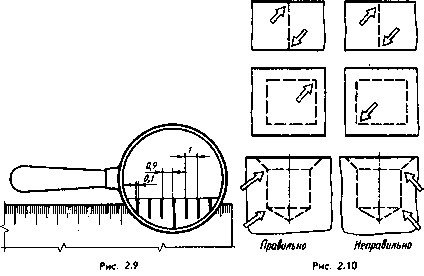
In Fig. Figure 2.10 shows cases of correct and incorrect application of dashed lines.
The distance between any two parallel lines should not be less than 0.8 mm, and better - 1.00 mm (see Fig. 2.5).
Line types
Any drawing line is carried out strictly in accordance with GOST 2.303-68. The standard establishes nine types of lines of varying thickness and style.
The thickness of the main line is designated S. The thickness of other lines is selected depending on S. Each line has its own purpose and outline. Table 2 provides basic information about drawing lines. Almost all types of lines in a drawing are made using drawing tools.
Drawing lines
1. Solid thick main - used to create visible contour lines and section contour lines. With this line you will outline the inner frame of the drawing, the columns of the main inscription. The thickness of the solid main line (S) is selected in the range from 0.5 to 1.4 mm.
2. A solid thin line is intended for applying dimensional and extension lines, applying shading, drawing shelves of leader lines, to depict imaginary lines of transition from one surface to another. Line thickness can be selected from S/3 to S/2.
3. A solid wavy line is used to depict a cliff line, delineating a view and a section. Line thickness from S/3 to S/2. This type of line is done by hand.
4. Solid thin with a break. This line represents long break lines. Line thickness from S/3 to S/2.
5. The dashed line is used to depict invisible contour lines, invisible transition lines. The stroke length is chosen from 2 to 8 mm, the distance between strokes is from 1 to 2 mm. Line thickness from S/3 to S/2.
6. The open line is intended to depict the location of the cutting plane when constructing sections and sections. Line thickness from S to 1.5 S.
7. A dot-dash thin line is used to depict axial and center lines. The stroke length is selected from 5 to 30 mm, the distance between strokes is from 3 to 5 mm. Strokes alternate with dots. Line thickness from S/3 to S/2.
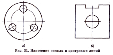
When depicting a circle, the strokes of the dash-dotted line must intersect in the center of the circle, and therefore the line is called the dash-dotted center line, thereby emphasizing its purpose (Fig. 31).
The dash-dotted (axial and center) line should protrude beyond the contours of the image of objects by 3-5 mm (Fig. 31, a). If it is necessary to set the center of the circle for a hole with a diameter of less than 12 mm, then the center lines are made with one stroke (Fig. 31, b). Figure 31 shows the application of axial and center lines.
8. A thick dot-dash line is used to depict the surface to be heat treated or coated (not used in the school course).
9. A dot-dash thin line with two dots is used to depict fold lines on developments, to depict parts of products in extreme or intermediate positions. The length of the stroke is from 5 to 30 mm, the distance between strokes is from 4 to 6 mm. Line thickness from S/3 to S/2.
In Fig. Figure 32 shows a drawing of a product in which some types of lines are used. As you look at it, pay attention to the following:
1. The drawing is made using various types of lines.
2. The thickness of lines of the same type in the drawing should be the same.
3. The smallest thickness of lines drawn in a pencil should be 0.3 mm, and the smallest distance between line strokes should be from 0.8 to 1.0 mm.
4. Strokes, spaces between strokes for the same type of lines should be approximately the same length.
5. The dot-dash line intersects in the center of the circles with strokes and ends with the image of a stroke.
6. Drawing images of objects begins with drawing axial and center lines, from which all subsequent constructions are made.


