Structural elements of parts and products. Structural characteristics of the part. Physical, mechanical and technological properties of materials
Structural forms of parts are formed by a combination of different geometric surfaces. Separate such surfaces are elements of parts.
On fig. 145 shows a gearbox shaft with bearings and a gear. The main elements of the shaft are: chamfers 1; necks for gears and bearings 2; grooves 3; shoulder 4; keyway 5; center holes on the ends of the shaft 6.
We use one of the most powerful and most modern laser machines, which allows us to cut stainless steel up to 15mm, aluminum up to 8mm and ferrous metal up to 20mm. Due to maximum productivity and high quality, the equipment of our metalworking complex is ideal for processing individual orders, as well as for large batches of products. Along with the automation of production, a professional approach and careful attitude of employees to the results of laser cutting is still an important element for us.
Rice. 145
The necks, shoulder and keyways are mated (connected) with the corresponding elements of other parts of the assembly unit. Their dimensions, shape and location are consistent with the mating parts and are established on the basis of calculation and design considerations determined by the value and operation of the assembly. Such elements are called constructive.
Physical, mechanical and technological properties of materials
Sheet metal laser cutting technology. Laser metalworking is an automated and high-tech process that has a number of important advantages over other metal cutting methods. Additional part configuration - the geometric shape of the parts and the level of complexity of the contour of the part intended for laser cutting is actually only limited by the imagination of the designer or design engineer. The technology of laser cutting of metal makes it possible to produce very small holes in materials with a diameter of 1 mm or more. The quality of the cutting surface, the absence of residual deformation on the part - the computerization of the process and the absence of mechanical impact make it possible to avoid residual deformation of the cutting contours, as well as to minimize temporary deformations, since during laser cutting there is no direct contact with the metal surface. In addition, due to the characteristics of the laser temperature, the edge of the part is braked, which increases its strength. High accuracy of laser cutting - there is no need for further mechanical reduction of the part to the specified dimensions, since the accuracy of laser cutting is 1 mm. Low Material Waste - Laser cutting of metal is carried out according to ready-made schemes and drawings, which makes the process almost useless due to the minimization of finishing and residues. Laser metal cutting allows significant savings on small batches of products, since it is more practical and reasonable to perform laser tailoring of metal than to additionally purchase rather expensive molds and dies or dies, especially for small-scale production. Speed and automation of the laser cutting process - automatic metal cutting differs from other methods in its speed, which is a significant advantage, especially for large-scale industrial orders. A significant reduction in the human factor due to production automation allows you to significantly optimize costs and at the same time improve the accuracy of laser tailoring and the final product quality. Laser cutting of various metals. Laser cutting does not deform thin metal plates and is safe for materials with a mirror and glazed surface. The laser beam allows for easy work of additional structural elements and marking of parts, which simplifies the further design of bending, bending and welding.
The emergence of other elements - chamfers, grooves, center holes is due to the technological requirements for the convenience of manufacturing the part and assembling it with others. So, chamfers on the parts are necessary for the convenience of assembling the parts (without tearing the ends). Grooves are needed to exit the grinding wheel when grinding the necks of the shaft, and the center holes serve as a base for processing the shaft (the shaft is installed on the machine in the centers). Elements of parts associated with the operations of their manufacture are called technological.
Introduction to thumbnails
It is also possible to perform technological laser engraving of the part. Technical capabilities of the equipment. For your convenience, we offer a cost estimate for laser cutting based on the length of the contours of the part to be cut. If you know the summary perimeter of the part outline and the length of the material, you can estimate the cost of manufacturing your parts yourself. You can get an estimate with the Tube and Plate Cutting Calculator.
We take full responsibility for the result of the execution of the order, and therefore a high level of professionalism and close attention are the key principles of the work of engineers. The quality of the parts made depends on the metal from which it will be made.
From the considered example, it can be seen that the methods of manufacturing parts often require the introduction of elements of an exclusively technological nature into their design. But sometimes the same element can be both constructive and technological.
No part, as a rule, can be designed outside the assembly unit of the machine in which it is included. Therefore, the parts get their shapes and sizes in the process of developing the designs of assembly units.
The resulting products undergo an initial multi-stage quality control. The complex of these events allows us to take a leading position in the metalworking industry of Ukraine and abroad. If you still have questions or need to specify - we will be happy to provide you with all the necessary information in a convenient way for you.
Please indicate: whose metal, form of payment, desired conditions in case of urgency, number of parts, whether you need delivery and where. Of course, include the contact phone number and the responsible person. An example of a prefabricated modular building system component is aluminum cladding. Such a cladding is typically placed and fixed on the outside of a fiberboard or wood panel. Advantageously, the configuration according to the invention makes it possible to create a structural element that includes a pre-finished skin, so that, for example, when a wall is, for example, built from several structural elements, there is no need for additional cladding, application, etc. constructed wall. This concerns whether the wall is a sidewall, floor, roof, ceiling, etc. preferably, the structural element can act as a load-bearing element. Preferably the element is elongated and structural element includes an end that protrudes from the facing. Preferably structural element is hollow. Preferably, the end is adapted to be placed in a channel. If the structural element is configured to include an end and an opposite end protruding from the shell, the structural element may be secured between two C-shaped support elements. Alternatively, the end is adapted to fit and fixable in the inner corner of the L-section support member. Preferably, the connecting means are formed on opposite sides of the sheath. The connection means may include a tongue formed on one said side of the shell and a groove formed on the opposite said side. Alternatively, the connection means may include additional stepped formations. Coupling means helping to place one structural element directly adjacent to another. Preferably, the core is rectangular in cross section. Preferably the core is metal, glass fiber or carbon fiber. Preferably, the shell comprises cement, concrete, fiber cement, fiberglass or cellulose. Cellulose can be obtained from recycled paper. According to a second aspect of the invention, a method of construction is provided, including forming a wall by placing two or more structural elements according to the first aspect of the invention in a parallel relationship, whereby the connecting means on adjacent structural elements mutually abut and align with each other. Advantageously, the configuration of the structural members allows the design of the panel or wall to be improved for use as a sidewall, floor, retaining wall, etc. preferably, the structural elements are held parallel to each other by two support elements at respective ends of the structural elements. Preferably, the ends of the structural elements are attached to the support elements when the structural elements are in position. Preferably, the support members are elongated and C-shaped in cross section. In the figures, like reference numerals designate like parts. The board can be made to any desired length, depending on the desired function or end use of the board 100. The board 100 includes a structural element in the form of a hollow closed sectional bar 102. The core 102 is usually made of steel, although it may alternatively be made of aluminium, carbon fiber, fiberglass or any other suitable construction material. Cladding 104 is formed from at least a portion of core 102. Cladding 104 is typically a cement-based material such as fiber cement, although it could alternatively be made from fiberglass; ceramics; foamed polymer materials such as polystyrene; or a cellulose-based material such as recycled paper or wood pulp; etc. the type of material used to form the lining 104 will depend on the desired appearance finished product . For example, if a sandstone appearance is desired, the cladding may be made of glass-modified cement. Support means in the form of a respective tongue 105 and groove 106 are formed in respective first and second opposite longitudinal edge portions 107 and 108 of plate 100. The tongues 105 and grooves and 106 layers provide mutual abutment and alignment on adjacent beads 100. place a test connection between tongue 105 and groove 106. The test connection is typically a rubber band or silicon tube. This improves the reduction of sound, heat, and water transmission through the junction between adjacent mutually adjacent and aligned boards 100. First and second opposing surfaces 117 and 118 are also formed in shell 104, typically in a flat design. In alternative embodiments, one or both faces 117 and 118 are formed in different aesthetic shapes. The thickness of the edges 117 and 118 of the sheath 104 around the core 102 is typically about 10 mm, although in some cases it may be about 3 mm. The depth of edges 117 and 118 is usually 300 mm. The first and second ends 120 and 122 of the core 102 extend beyond the sheath 104. This should allow the ends 120 and 122 of the board 100 to fit in the channel 124 of the support member 126. C-sections In an alternative embodiment of the board 100, the first and second ends 120 and 122 the boards are flush with the first and second respective ends 128 and 130 of the shell 104. The board 100 may be used in a building system including any of the retaining walls, multi-wall buildings, and the like. board 100 in such a system can be used to build walls in the form of side walls 131 or portions thereof, interior partitions, floors 132, ceilings 133, roofs 134, and so on. in one embodiment, to assemble a wall using a plurality of planks 100, two C-section support members 126 are anchored in a vertical position relative to the ground in concrete pillars 135 that are set into the ground. The C-segment support elements 126 are positioned with their respective channels 124 facing each other. The C-section support elements 126 are spaced apart by a predetermined distance, approximately the width of the desired wall. In determining the width of the wall and the C-section support members 126, suitable planks 100 are selected to construct the desired wall, where the distance between the first and second ends 128 and 130 of the shell from the plurality of planks 100 to the set between the members 126 is approximately the distance between the support members C- section 126. The boards 100 are then positioned and fixed between the C-section support elements 126 one above the other, where immediately adjacent first and second sides 107 and 108 adjacent boards 100 mutually abut. This described arrangement can be used to construct a single side wall, such as a retaining wall. In the method of constructing, for example, a building, a plurality of side walls 131, floors 132, ceilings 132 and a roof 134, etc. installed. Then, the main horizontal beams 138 are attached between the two support posts 137, and the auxiliary horizontal beams 139 are attached between the main horizontal beams 138. After the support posts 137, the main and auxiliary horizontal beams 138 and 139 are in place, the C-section support elements 126 are then attached at the required locations on the pedestals, complementing the frame superstructure suitable for the receiver boards 100. In an alternative embodiment, the elements 126 are attached to the pedestals 137 before the pedestals are installed on the concrete slab 136. This ensures the board 100 is in position on the carrier. element 126. In an alternative embodiment, holes 144 may be pre-formed at first and second ends 120 and 122 and fasteners such as a screw, bolt, nail, etc. Placed through respective holes 144 at the first or second end and 122 of the board and pre-holes 146 in the support member 126. c-sections in the preferred embodiment of the present invention, the ends 120 and 122 of the cores 102 of the boards 100 used to build the floor 132 do not protrude from the respective ends 128 and 130 of the cladding 104. This is so that the ends 120 and 122 of the cladding 104 are flush with the adjacent wall 131. The ceiling 133 or roof 134 is constructed in the same manner as described in relation to the construction of the floor 132. If the length of the board 100 is used for construction floor 132 or ceiling 133, is a standard length of 3.6 m or less, auxiliary beams 139 are not required. Hollow support posts 137 and main and auxiliary horizontal beams 138 and 139 also allow for electrical services that can be continued through walls, floors, etc. or connected to electrical services. One of skill in the art will appreciate that cores 102, posts 137, etc. also allow the passage of water, telephone and gas services and air conditioning ducts. In the case of air conditioning, this can be used to heat or cool the side walls 131, floors 132, or ceiling 133, or direct hot or cold air to an outlet to blow air into a specific room, for example. Both quoid 164 and covers 166 are typically connected to their respective support posts 137 by bolted mounting plates 168 to posts 137. In these embodiments, when the second quoid 164 or cover 166 is positioned above the first attached quoin 164 or cover 166 as needed , the stepped portion 174 is located in a recess 172 between the lower projection 176 and the main body 178 of the quoin 164 or cover 166. The thickened facing portion 183 is both aesthetically pleasing and carries a drip groove 184. If water, such as from rain, runs down this board 100, the thick facing portion 183 helps direct water away from the window 181 or door 182, and the drip groove 184 helps prevent water from moving across the underside 185 of the board 100 and into the building. The fire flasher 187 is also placed between the window or door frame and the board 100 directly above the window or door frame and between the board 100 just below the window frame. The preformed wall 131 is then placed in position on the building frame structure, which includes the 18-section support members. The board 100 is then attached to the support post 137 with a screw or the like. which connects between support post 137 and core 102. In this embodiment, covers 166 are not required. Also in this embodiment, quoids 164 are also not required. Now that the preferred embodiments of the invention have been described, it will be apparent to those skilled in the art that the structural element, construction method, and construction systems have at least the following advantages: 1, they offer a cheaper alternative to conventional construction methods; 2 the hollow nature of the structural element acts as an acoustic damper and insulator; 3 the resulting building structure has high structural integrity as each structural element is connected to the superstructure; 4 they provide a relatively inexpensive kit assembly system that allows an aesthetic building to be built; and 5 resulting building, retaining wall, etc. relatively easy to install, can be assembled without the use of heavy machinery and with reduced trader activity. Although the invention has been described with reference to specific examples, it will be appreciated by those skilled in the art that the invention may be embodied in many other forms. With the help of this utility in graphical form it will be possible to obtain valuable information that will complement the lists by supporting the files and memories generated in the chapter of the building.
From the point of view of applicability and distribution in mechanical engineering, parts can be divided into standard, unified and original. Standard parts include parts supplied in accordance with state, republican and industry standards, as well as enterprise standards. Unified ones include those borrowed from another product, i.e., previously designed as original ones. Original parts are designed for a specific machine and, as a rule, they do not have a similar pattern.
The shape and size of parts in practice is carried out using a variety of technological processes described above. The drawing of a part, as a rule, predetermines the technology of its manufacture.
One and the same part and machine can be designed in several ways. Creating a car is a complex creative process that does not have an unambiguous solution. A large number of diverse and often conflicting requirements are imposed on a new design: the smallest mass, the necessary durability, strength, certain dimensions, low cost, ease of maintenance, etc. In most cases, it is impossible to fulfill all the conditions at the same time, and the solution is almost always a compromise.
When choosing final decision of the many options, they stop at the one that, judging by the drawing, is the most technologically advanced. According to GOST 14.205-83 manufacturability of the design products are a combination of its properties, manifested in the possibility of optimal (the most favorable technical and economic) costs of labor, funds, materials and time in the technical preparation of production, manufacture, operation and repair.
The type of manufacturability is determined by the features that characterize the area of manifestation of the manufacturability of the product design. On this basis, the following types of manufacturability are distinguished: production and operational.
The production manufacturability of the product design is expressed in the reduction of the cost of funds and time for: design preparation of production (KPP); technological preparation of production (TPP); manufacturing processes, including control and testing.
The operational manufacturability of the product design is expressed in the reduction of time and money spent on maintenance and repair of the product.
The main factors determining design manufacturability requirements, are: type of product; issue volume; production type.
The type of product determines the main design and technological features that determine the basic requirements for the manufacturability of the design.
The volume of output and the type of production determine the degree of technological equipment, mechanization and automation of technological processes and the specialization of the entire production.
V general view design manufacturability tasks that should be taken into account when developing new original parts are shown in fig. 146. It can be seen from Fig. 146 that the concept of manufacturability is interpreted very broadly and can be formulated as follows: the task of manufacturability of a design is to designate a machine with such shapes, manufacturing accuracy and technical qualities of parts, as well as the choice of such materials, workpieces and technological processes and assigning such interfaces of parts to assembly units and to the machine, which, in combination, would ensure the achievement of: optimal design parameters that require the physical and technical properties of parts and the machine as a whole; the most simple, productive and economical production process for the manufacture of machines; the highest performance of the machine and its components.
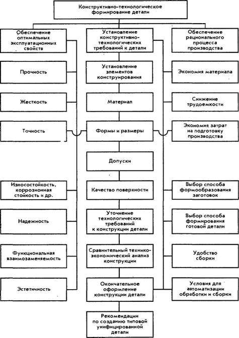
Rice. 146
Manufacturability is not a universal state of a once designed part or machine. It varies depending on the technological capabilities of the manufacturer. For a plant with a powerful foundry base, the cast option may be the most technologically advanced (Fig. 147, I, III), for a metal structure plant - welded (Fig. 147, II, IV). Manufacturability largely depends on the serial production. In individual production, welding is the most convenient. On fig. 147, II, IV shows two variants of the welded design of the lever. The latter is a lightweight design. In both cases, individual elements of the part - two bushings and a heel - are welded to the figured bar. In serial production for large-sized parts, it is most convenient to cast into the ground (Fig. 147, I), in large-scale production - casting into a chill mold or into shell molds (Fig. 147, III). Hence, the principle of manufacturability requires the creation of machines that are most adapted to given specific production conditions.
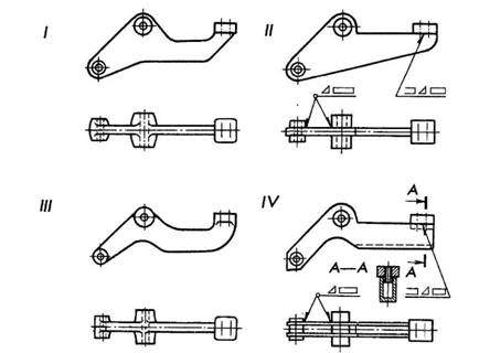
Rice. 147
Suppose now that you have before you the drawings of the designed product in several possible versions. What criteria should be followed in order to choose the best option among them?
Evaluation of manufacturability of product design can be of two types: qualitative and quantitative.
The type of assessment characterizes the method of comparing design solutions and a reasonable choice of the optimal design option for the product. Qualitative assessment is associated with the choice of the best design solution and determining the degree of difference in the manufacturability of the compared options. A quantitative assessment is expressed by an indicator, the numerical value of which characterizes the degree of satisfaction of the requirements for the manufacturability of the design.
For all types of products in accordance with GOST 14.201-83, the following tasks are set when testing the design for manufacturability:
1 - reducing the complexity of manufacturing the product. It depends on many factors, the main of which should be considered standardization, unification of the components of products and their elements, typification of technological processes for manufacturing, maintenance and repair of the product;
2 - standardization of the component parts of the product, which are assembly units (blocks, assemblies) or parts (fasteners, etc.). Using standard components in the design of the product, they ensure their interchangeability;
Unification of the components of the product. It includes: the use in the designed products of structural components processed for manufacturability and mastered in production, reducing the number of items and sizes (see Chapter I, paragraphs 1 and 4), component parts of the product and materials used;
1 - unification of structural elements of parts. This applies to fits, accuracy classes, surface roughness, threads, slots, keys, tooth modules, hole diameters, etc.;
2 - the possibility of using standard technological processes for assembly, processing, control, testing, maintenance and repair. The use of standard technological processes creates conditions for increasing the level of its mechanization and automation, reducing the time for manufacturing, servicing and repairing products.
The sequence of solving the problems of manufacturability of the design at various stages of design is shown in Fig. 148. From fig. 148 shows that highest value have constructive solutions at the first stages of design, when the main structural and technological features of the structure are determined, which mainly predetermine its manufacturability.
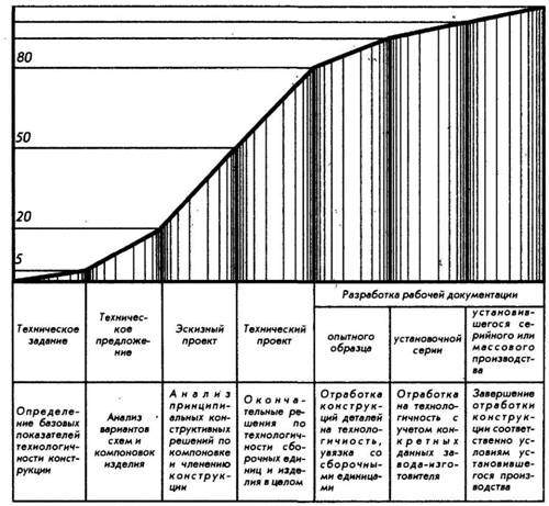
Rice. 148
Let us now get acquainted with the technological requirements for both individual parts and the mechanism, the machine as a whole.
The accumulated experience in the field of mechanical engineering technology has made it possible to outline specific examples of design solutions that can be considered as recommendations that deserve attention when designing parts, assembly units, machines and mechanisms.
Constructors are mostly people with imaginative thinking and good visual memory. For them, drawings and sketches say much more than many pages of explanations. Therefore, almost every statement below is accompanied by constructive examples.
GENERAL INFORMATION ABOUT SKETCHES
A sketch is a drawing made by hand without the help of drawing tools and fixtures on a visual scale, if possible, observing the correct ratio between the dimensions of all parts of the part.
According to the nature of the application, sketches are divided into design sketches, that is, made before the manufacture of an object, and sketches from nature - after the manufacture of the object. The need for the latter arises mainly when replacing a partially worn out or completely failed original (non-standard) part, if it is not in stock, as well as during installation and repair work, when for some reason the individual dimensions of the part are unknown, allowing you to correctly connect and coordinate it among other parts of the mechanism, machine. In some cases, for example, in experimental production, when the execution of a working drawing is time-consuming, the sketch is the only document by which the part is made. Therefore, it, like a drawing, must give a complete picture of the external and internal forms details, its dimensions, processing, surface roughness and have all the explanatory inscriptions necessary for its manufacture.
Sketches are recommended to be done on plain checkered paper. The cage facilitates freehand drawing of horizontal and vertical lines and circles, hatching at an angle of 45 o and symmetrical (with respect to axial and center lines) construction of projections. A sketch is drawn up with a frame and a title block in the same way as a drawing. For work, it is best to use soft pencils "TM" or "M" and "2M". Sketches are carried out in such a scale that even small details can be marked with all dimensions, designations and inscriptions. For digital and text inscriptions and symbols, a standard font is used, at least 3.5 mm in size, which is dictated by ease of reading.
For each original part included in the assembly unit, except for the standard ones, a separate sketch is made. The sketch must contain complete description details:
1) clear geometric shapes;
2) geometric dependencies of elements interconnected by sizes;
3) technological information on tolerances and fits for controlled dimensions, as well as instructions on roughness and special surface coatings;
4) material characteristic: indicators of the mechanical or special properties of the material, such as heat treatment or acid resistance, etc.
THE CONCEPT OF THE STRUCTURAL AND TECHNOLOGICAL ELEMENTS OF THE DETAILS
Before sketching a part from nature, it is first necessary to clearly understand the geometric shape of its constituent elements. To do this, you should mentally divide the part into geometric bodies.
On fig. 9.1 shows two methods: 1) when the geometric shape of the part is considered as a "sum" geometric bodies, its components, and 2) when, in the process of shaping, the details were isolated elements that can also be represented in the form of geometric bodies.
The structural forms of the part are formed by a combination of various geometric surfaces. Separate such surfaces are elements of parts. Let's show this on the example of a gearbox shaft with bearings and a gear wheel (Fig. 9.2). The main elements of the shaft are: chamfers 1, necks for gears and bearings 2, grooves 3, shoulder 4, keyway 5, center holes at the ends of the shaft 6.
Rice. 9. 1. Analysis of the geometric shape of the part:
a - the shape of the part is considered as the "sum" of geometric bodies;
b - the shape of the part is considered as a "difference" of geometric bodies

Structural and technological elements of a stepped shaft
The necks, shoulder and keyways are mated (connected) with the corresponding elements of other parts of the assembly unit. Their dimensions, shape and location are consistent with the mating parts and are established on the basis of design and design considerations determined by the purpose and operation of the product. Such elements are called constructive.
The emergence of other elements - chamfers, grooves, center holes - is due to the technological requirements for the convenience of manufacturing a part and assembling it with others. So, chamfers on the part are necessary for the convenience of assembling the product (without tearing the ends). Grooves are needed to exit the grinding wheel when grinding the necks of the shaft, and the center holes serve as a base for processing the shaft (the shaft is usually installed on the machine in the centers). Elements of parts associated with the operations of their manufacture are called technological.


