The part numbers on the assembly drawing are indicated. General rules for the execution of assembly drawings. Specifying Item Numbers
Assembly drawings are performed when the product consists of several parts. This drawing consists of images of the parts that make up the product and the information necessary for their manufacture and assembly.
An assembly drawing is a document containing an image of an assembly unit, giving an idea of the location and interconnection of the components connected to each other, and providing the possibility of assembling and controlling the assembly unit.
This makes maintenance work easier because, in addition to what was mentioned in the previous section, it allows identification of lubrication points, temperature control points, spare parts needs, etc. it provides an image that gives an idea of the operation of the represented machine or mechanism.
In the overall set of the drawing, we can see the relationship, position, and agreement between the various subsets; while each of the subsets of drawings clearly shows the various elements that make it up. It also gets the name of an assembly drawing because it serves as a guide for how to assemble a mechanism from loose parts.
The assembly drawing should give a complete picture of the form, functionality and composition of the assembly unit.
According to the assembly drawing, it is possible to assemble the simplest assemblies and the most complex machines and technical devices from individual parts, parts of mechanisms.
According to the assembly drawing, you can imagine the relative position of the components, how the parts are connected to each other and the principle of operation.
This type of drawing is used by manufacturers to show the overall dimensions of a machine, installation, etc. in catalogs. In ensemble drawings, it is necessary to draw the necessary views in order to be able to see and refer to all the parts that make it up, and not the need to define all the structural parts of the same ones, since they will be fully defined in the corresponding exploded drawings, and not that such parts have an obvious value to execute assembly assembly or to interpret it.
The correct interpretation of a set of drawings requires a distinction various parts, which constitute it, for which the following rules must be taken into account: the contact surfaces between two adjoining parts are represented by a single line of the same thickness as that used for any visible line, without having to use different lines, or separations between the two parts. When the whole is presented in section, different parts of the same piece must have the same type of scratches; however, adjusted parts shown in cross section will have dotted lines sections facing away from each other.
The assembly drawing must contain:
1) image of the assembly unit;
2) the required dimensions. The assembly drawing must necessarily contain dimensions that characterize the product as a whole, as well as those that must be maintained during assembly and control of the manufactured product ( dimensions, i.e. the largest external dimensions of the product in three dimensions (height, length, width); installation size- the size that determines the position of the object at the installation site or the position of the component when it is installed in the product; connecting dimensions, i.e., the dimensions of the elements of the part, product, providing the possibility of attaching them to another product; mounting dimensions, i.e. the dimensions necessary for the correct installation of parts relative to each other, for example, the dimensions between the center and center lines; operating dimensions, indicating the extreme positions of the moving parts of the products, for example, the stroke of the piston, lever, engine valve);
If this is not possible because more than two flat figures are shown in the section, the scratches differ from the areas of each part by different distances and are proportional to the total surface to be scratched. Sections of very small pieces have turned black. If there are several of these adjacent pieces, they are represented by a blank with a thickness of at least 0.7 mm. Solid components such as shafts, shafts, screws, pins, keys, etc. Not longitudinally divided and therefore not scratched; in turn, the rolling elements of the bearings are also not shown in cross section.
3) item numbers;
4) technical requirements;
5) technical characteristics of the product (if necessary);
6) specification.
Specifying Item Numbers
The components and specified materials of the assembly unit shown on the assembly drawing must have numbers that are applied in accordance with GOST 2.109-73:
1. All components of the product on the assembly drawing are numbered in accordance with the position numbers indicated in the specification of this assembly unit.
2. Position numbers indicate on the shelves of leader lines drawn from the images of the component parts. The end of the leader line that intersects the contour of the part ends with a thickening in the form of a dot. The leader line and the shelf are drawn by a solid thin line. Position numbers should be indicated on those images in which the corresponding components are projected as visible, as a rule, on the main views or sections that replace them.
The representation of threaded connections will take into account that external threads hide the representation of internal threads. If there is no doubt or ambiguity, the drawing of the standard elements may be reduced to symbolic strokes or to a simplified representation in accordance with the specifications established by the normalization appropriate to each case. When the set element is movable, the extreme positions can be represented by thin and two-point lines. 60°.
The sequence and basic techniques for reading drawings
Once the assembly drawing is completed, it will be examined if the assembly provided for each of the parts is feasible and rational. They are dimensions that ensure the correct operation of the mechanism by setting the appropriate adjustments.
3. Position numbers are placed parallel to the main inscription of the drawing outside the image outline and grouped into a column or line, if possible on the same line.
4. Position numbers, as a rule, are indicated on the drawing once. It is allowed to repeatedly indicate the position numbers of the same parts of the product, while all repeating position numbers are highlighted with a double shelf.
5. The font size of the position numbers should be one or two sizes larger than the font size adopted on the drawing for dimensional numbers.
6. Leader lines should not intersect with each other and, if possible, should not be parallel to hatch lines and dimension lines
7. It is allowed to draw a common leader line with a vertical arrangement of position numbers:
for a group of fasteners related to the same attachment point;
for a group of parts with a clearly expressed relationship, excluding a different understanding, and when it is impossible to draw a leader line to each component in the drawing. In these cases, the leader line is taken away from the part, the position number of which is indicated first.
These are dimensions that define the distance between certain pieces to determine their position. These are the dimensions that provide overall dimensions mechanism. If one of these dimensions has a variable value, two limit values of this size are indicated. In some cases, the assembly drawing may include dimensions corresponding to the processing work that is intended to be done during the assembly process or after the assembly is completed, for example, for multi-section drilling, etc. From the above, it is necessary to establish standards for identifying the parts of a set so that each piece has the same identification in all documents in which it is reflected.
Conventions and simplifications allowed on assembly drawings
In order to save time on assembly drawings in accordance with GOST 2.109-73, it is allowed to apply simplifications and conventions
1. The moving parts of the assembly unit are depicted in extreme or intermediate positions. The assembly drawing conditionally depicts:
a) the coils of the spring are depicted by straight lines connecting the corresponding sections of the contour of the figures of the section of the spring;
An example of reading and detailing the assembly drawing of the product "Vise"
In general drawings, each part will be accompanied by a correlation number that identifies it. To distinguish them from other indications, the nominal height of these numbers must be twice the nominal height and in no case be less than 5 mm; even, can be framed with a circle. Preferably, the order of the sequence of numbers is related to the assembly order.
Specifying Item Numbers
Identical elements of the same set must be identified by the same reference, indicating an identification label to one of them, provided that there is no ambiguity; however, the total number of items equal to that specified must be recorded in the parts list. This line ends at a point if it ends inside the piece, or an arrow if it ends at the outline of the part. For this reason, the reference lines will never be a continuation of any other line of the figure. They will not interfere with any other information or shorten themselves.
b) plugs of plug valves - in the "open" position;
c) jacks in the position of the beginning of the lifting of the load;
d) vise with shifted jaws;
e) springs in section are represented by two turns from each end.
2. Welded, soldered, glued and other products made of a homogeneous material in an assembly with other products in sections and sections are hatched as a monolithic object (in one direction) with the image of the boundaries between the parts of such a product with solid main lines.
Conventions and simplifications allowed on assembly drawings
It must be ensured that the layout of the numbers is aligned in rows and columns in order to achieve greater aesthetics. The same reference line may include identification marks corresponding to several related elements. In complex sets divided into subsets, each of these subsets must be identified with one reference; identifying the various components of each subset by a decimal system. For this reason, the labels will be formed by several groups of numbers, separated by dots or slanted lines, and arranged in such a way that the first group on the left identifies the set of higher-ranking chunks, next to the units that make up the previous set, and so on. down to the simplest elements to be identified by the group on the far right.
3. It is allowed not to show on the images of the assembly unit:
a) small structural elements on the surfaces of parts: chamfers, annular grooves for the exit of the cutting tool, knurling, etc.;
b) gaps between the rod and the hole;
c) the image of the thread on the end view.
4. In sections, according to the rules of GOST 2.305 - 68:
A parts list is added to the installation drawing above the labeled box; will have the same width as this and as many lines as the pieces concatenate the set. The names of the various sections in which the list of sections is divided will be indicated at the bottom, designating the sections from bottom to top in a correlation order according to their identifying mark. If a set has many parts, the parts list can be made separately in a standardized format and must be identified with the same drawing number as the set drawing.
The titles of the various sections will be listed at the top of the parts list, marking the parts from top to bottom in a correlation order according to their identification label. The content of the parts list is flexible so companies can tailor the information it displays, however you can enter information under the following headings: The label column indicates the reference number of each part shown in general drawing. The denomination column indicates the full designation of the work in the singular, adding, if necessary, additional data.
a) bolts, screws, studs, dowels, rivets, non-hollow shafts, spindles, connecting rods, handles, etc. at a longitudinal section they are shown undissected;
b) spokes of flywheels, pulleys, gears, thin walls such as stiffeners, etc. are shown unhatched if the cutting plane is directed along the axis or long side of such an element.
If it is a standard part, its standard notation should be used. The number of pieces columns indicates the total number of pieces of each type or label and is therefore identical to those needed to form a complete set. The standard column refers to the norm applicable in the case of standard parts.
The manufacturer column indicates, when using components supplied by other manufacturers, the name of the manufacturer. In the reference column, when using components supplied by other manufacturers, the full reference is indicated in accordance with the manufacturer's catalog. The license plate column indicates, in the case of non-standard components, the number of the cut plane in which the component is defined. The material column indicates the type and quality of the material the part is made with. If it is a standard material, its standard designation should be used.
5. Bolts, screws and studs are depicted in assembly drawings in a simplified way.
Specification
Each Assembly drawing accompanied by a specification.
Specification - the main design document, made in the form of a table, which lists the names, position numbers of all components of the assembly unit and indicates their number.
The parts list may contain other information necessary to define the product definition, such as overall dimensions, specific gravity, terms of delivery, observations, etc. This type of drawing will include: shapes and dimensions various details designs, tolerances, surface finishes, treatments and coatings, materials, etc. As well as all the information necessary for the manufacture of various products; ensuring the assembly and correct operation of the mechanism in which they are inserted.
In general, industrial graphics rules relating to the drawing of independent parts will be applied using the gaze system; ordering them according to the specified normalization when projecting the piece into the first dihedral. Each part will be represented by views, sections, sections and details necessary and sufficient to clearly define the shape of all its structural details.
In the specification, the documentation and components of the assembly unit are listed in a certain sequence: documentation, complexes, assembly units, parts, standard products, other products, materials, kits.
The specification is carried out on separate sheets (one or more) of A4 format or placed directly on the assembly drawing, made on A4 format, if there is enough space to accommodate it. The specification is carried out before the position numbers of the parts included in the assembly unit are applied to the assembly drawing. It is necessary for the manufacture of the product.
Must match the data set in the general drawing. This is because the overall design does not have to show the full shape of all the details. The pieces must be drawn with respect to the position they represent in the set. If there is a part that can take different positions, it will be presented in the appropriate position for processing it. Start cutting with the simplest parts in terms of their shape. The imaginary elimination of these parts from the assembly makes it easier to determine the shape of the most complex parts.
Each part will be drawn in the most convenient scale; in any case, if possible, standard scales are used. All details must be calculated until the dimensions of each of them are fully determined, regardless of whether there were any details, such as the diameter of the hole or thread, in the other part. When cutting parts, it is recommended to consult the standards corresponding to the standard parts in order to be able to set the dimensions of the parts that comply with them.
After each section of the specification, in accordance with GOST, free lines are left and position numbers are reserved for the possible introduction of additional products.
Filling in the specification column
done from top to bottom as follows:
1. In the column "Format"
indicate the formats of documents, the designations of which are recorded in the column "Designation".
for documents recorded in the sections "Standard products", "Other products" and "Materials", the column is not filled in.
for parts for which drawings are not issued, the column indicates CU (without a drawing).
2. In the column "Zone"
indicate the designation of the zone in which the recorded component is located (when the drawing field is divided into zones in accordance with GOST 2.104-2006).
3. In the graph "Pos."
(Position) indicate the serial numbers of the components included in the specified product in the sequence of their entry in the specification. For the sections "Documentation" and "Kits", the column is not filled in.
4. In the graph "Designation"
the designation of the document for the product is recorded in accordance with GOST 2.201-80.
Adding a part from a file
Analyze in the figure a set of functions performed by each of the parts that make it up. This will take into account a number of very important aspects, which must be taken into account when cutting to ensure the correct assembly and operation of the mechanism: Adequate settings, classifying them into: fixed, mobile and indeterminate. In this way, the measurement can be made in accordance with the function, indicating manufacturing tolerances that allow for appropriate adjustments. The usefulness of each surface, allowing them to be classified into: functional, supportive and free.
5. In the graph "Name"
indicate:
in the "Documentation" section, only the name of the document, for example, "Assembly drawing";
in the sections "Complexes", "Assembly units", "Details", "Kits" - the name of the products in accordance with the main inscription on design documents these products, for example, “Gear wheel”, “Sleeve”. For parts for which drawings are not issued, indicate the name and material, as well as the dimensions necessary for their manufacture;
in the section "Standard products" - the name and designation of products in accordance with the standards for these products;
in the section "Other products" - the name and conventions products in accordance with the documents for their supply, indicating the designations of these documents;
in the section "Materials" - designations of materials established in the standards for these materials.
6. In the column "Col."
(Quantity) indicate the number of components in one specified product, and in the "Materials" section - the total amount of materials per one product with an indication of the unit of measurement.
7. In the graph "Note"
indicate additional information for planning and organizing production, as well as other information related to the products, materials and documents recorded in the specification.
The sequence and basic techniques for reading drawings
Read assembly drawing
- this means to present the shape and design of the product, understand its purpose, principle of operation, assembly procedure, and also identify the shape of each part in this assembly unit.
When reading a drawing general view follows:
1. Find out the purpose and principle of operation of the product.
The necessary information about the purpose and principle of operation of the product is contained in the main inscription and description of the product.
2. Determine the composition of the product.
The main document for determining the composition of the product is the specification, in which the components of the product are classified into sections. To determine the position of a specific component of the product in the drawing, it is necessary to determine the position number in the specification by its name, and then find the corresponding leader line in the drawing. The specification also allows you to determine the number of products of each item.
3. Determine the purpose and configuration of the components of the product.
The purpose and configuration of the product is determined by the functional features of the product as a whole and its components. The configuration of the components is determined by their purpose and interaction in the process of work. When determining the configuration of the component parts, attention should be paid to the way they are connected.
4. Identify ways to connect the components of the product to each other.
The ways of connecting parts are due to the peculiarities of the interaction of the elements of the product during its operation. Connection methods can be identified from the general arrangement drawing and classified as detachable or non-detachable.
5. Determine the sequence of assembly and disassembly of the product.
One of the main requirements for the design of the product is the possibility of its assembly and disassembly during operation and repair. Only such a design can be considered rational, which allows assembly (disassembly) using the minimum number of operations.
The following drawing sequence is recommended:
1. According to the main inscription, set the name of the product, number, scale of the drawing, weight of the product, organization that issued the drawing.
2. Find out the content and features of the drawing (identify all the images that make up the drawing).
3. According to the specification, establish the name of each part of the product, find its image in all images, and understand its geometric shapes.
Since the drawings, as a rule, have not one, but several images, the shape of each part can be unambiguously identified by reading all the images in which this part is present.
You should start with the simplest parts (rods, rings, bushings, etc.). Having found a part on one (usually on the main) image using positional designation and, knowing the constructive purpose of the part, imagine its geometric shape. If this one image unambiguously determines the shape and dimensions of the part, then proceed in turn to identifying the forms of other parts; if one image does not reveal the shape or dimensions of at least one element of the part, then you should find this part on other images of the assembly drawing and make up for the lack of one image. The clarification of the shape of the part is facilitated by the fact that on all cuts and sections the same part is hatched with the same slope and the distance between the hatching lines.
At the same time, they use knowledge of the basics projection drawing(projection connection of points, lines and surfaces) and the conventions established by the ESKD standards.
4. Read the product description. If there is no description, if possible, read the description of a similar design.
5. Establish the nature of the connection of the component parts of the product to each other. For permanent connections, define each element of the connection. For detachable connections, identify all fasteners included in the connection. For moving parts, establish the possibility of their movement during the operation of the mechanism.
6. Determine which parts are lubricated and how lubrication is carried out.
7. Find out the order of assembly and disassembly of the product. In this case, it should be borne in mind that in the specification and on the assembly drawing, the order of recording and designation of the components are not related to the assembly sequence.
It is recommended to fix the order of assembly and disassembly of the product on paper in the form of a diagram or in the form of a record of the sequence of operations. The ultimate goal of reading a drawing, as a rule, is to clarify the design of the product, the principle of operation and the establishment of its purpose. In the educational process, the central place in reading the drawing is the study of the forms of individual parts, as the main means to clarify all other issues related to reading the drawing.
Drawing detail
Detailing is the execution of working drawings of a part according to a general view drawing.
Detailing
- this is not a simple copying of the image of details, but a complex creative work, including an individual assessment of the complexity of the forms of each detail and the adoption of the best graphic solution for it: the choice of the main image, the number and content of images.
The dimensions of the parts are measured in the drawing, taking into account the scale indicated by the main inscription. The exception is the dimensions printed on the assembly drawing. The dimensions of standard elements (threads, tapers, turnkey, etc.) are specified according to the relevant standards.
detailing process
it is advisable to divide into three stages: reading a general view drawing, detailed identification of the geometric shapes of parts and the implementation of working drawings of parts.
1. Reading a general arrangement drawing.
The result of reading a general view drawing should be an understanding of the composition of the parts included in the assembly, their relative position and methods of connection, interaction, constructive purpose of each part individually and the product as a whole.
2. Detailed identification of the geometric shapes of parts
to be drawn, in order to correctly select the main image, the number and content of other images in the working drawings. As the shapes of the details are revealed, the issue of choosing the main image and the need to perform other images for each detail should be decided, the image scale and format should be selected.
3. Making working drawings of parts.
make the layout of the drawing, i.e. outline the placement of all images of the part on the selected format.
draw the necessary views, sections, sections and detail elements in thin lines.
carry out remote and dimension lines. Determine the true dimensions of the elements of the part and put them on the drawing. Pay special attention to the fact that the dimensions of the mating parts do not have discrepancies. Determine the necessary structural and technological elements (chamfers, grooves, slopes, etc.), which are not shown in the general view drawings. The dimensions of the identified structural elements are determined not according to the general view drawing, but according to the relevant standards for these elements.
put down the roughness, based on the technology of manufacturing the part or its purpose.
circle the drawing and hatch cuts and sections.
check the drawing and, if necessary, make corrections.
fill in the main inscription, write down the technical requirements.
An example of reading and detailing the assembly drawing of the product "Vise"
A vice of this design is used to secure workpieces on metal-cutting machines.
The assembly drawing of the "Vise" product contains five images that give an idea of the product design. In place of the main view, a frontal section was made, necessary to clarify the relative position of the elements included in the product. In the top view, with the help of a local section, the connection of the plates (pos. 6) with the body (pos. 1) and the movable jaw (pos. 2) is shown. Section A-A gives an idea of the shape of the bases of the movable jaw (pos. 2) and the body (pos. 1), as well as the method of their connection. Section B-B gives an idea of the type of connection between the bearing (pos. 3) and the housing (pos. 1). The section B-B shows the shape of the plate (pos. 6) and the location of the screws (pos. 9) intended to fasten it to the body. The images show overall dimensions (length - 390 mm, width - 220 mm, height - 150 mm), installation dimensions (center-to-center distances of holes in the base of the housing - 155 and 160 mm, position of the screw axis relative to the base of the housing 95 mm). The specification for the drawing contains a list of all parts and standard products, their position numbers in the drawing and quantity. There are no assembly units in the composition of the product in question. The assembly drawing of the product "Vise" is accompanied by a description of the principle of operation of the product and information about the materials from which the parts are made (material of parts pos. 1–3 SCH 18-36 GOST 1412-70, material of parts pos. 4–7 St 5 GOST 380-71 ).
Rice. 1. Assembly drawing of the product "Vise"
Rice. 2. Product specification "Vise"
Disassembly (flash)
Assembly (flash)
Description of the product "Vise" and the principle of its operation
The vise is mounted on the table of a planer or milling machine and secured with six bolts (bolts not shown in Fig. 13.17). The workpiece is placed between two plates (pos. 6). The screw (pos. 5), which has a rectangular thread, is kept from axial movement by a ring (pos. 7) and a pin (pos. 12). To prevent the sleeve (pos. 4) from rotating around its axis, a screw (pos. 8) is installed. When the screw (pos. 5) is rotated, the movable jaw (pos. 2) will move along the guide groove of the body (pos. 1), clamping the workpiece with the plates (pos. 6).
Determination of the composition of the product "Vise"
The "Details" section lists the elements of the product that require the execution of working drawings for their manufacture: body, movable sponge, bearing, bushing, screw, plate, ring. The section "Standard products" is a list of parts used in the assembly and do not require drawings, since these parts are standardized. The specification also allows you to determine the number of elements of each item. To determine the position of a specific part in the product drawing, it is necessary to determine the position number in the specification by its name and find the corresponding extension line.
Determination of the purpose of the components of the product "Vise"
The main working element of the product in question (see Fig. 1) are clamping plates (pos. 6) that fix the workpieces. One of the plates is fastened with screws (pos. 9) to the body (pos. 1), and the other - to the movable jaw (pos. 2). Longitudinal movement of the jaw (pos. 2) along the guide groove of the housing (pos. 1) is carried out by rotating the screw (pos. 5). The transmission of movement from the screw (pos. 5) to the jaw (pos. 2) is carried out using a rectangular lead thread. The screw (pos. 5) is fixed in the bearing (pos. 3) by a bushing (pos. 4) and is kept from axial movement by a ring (pos. 7) and a pin (pos. 12). The sleeve (pos. 4) is kept from rotating by a screw (pos. 8). The bearing is attached to the housing (pos. 1) with studs (pos. 11).
Finding Ways to Connect Parts
According to the assembly drawing of the product (see Fig. 2) "Vise", it can be established that all connections belong to the detachable class: threaded (screw, pin connection), pin connection, with fit. The plates (pos. 6) are attached to the body (pos. 1) and jaw (pos. 2) with screws (pos. 9). The bearing (pos. 3) is attached to the housing with studs (pos. 11). The ring (pos. 7) and the screw (pos. 5) are connected with a pin (pos. 12). The sleeve (pos. 4) is fixed in the bearing housing (pos. 3) with a screw (pos. 8). A tight connection between the bush (pos. 4) and the bearing (pos. 3) is achieved by increasing the outer diameter of the bush in relation to the inner diameter of the bearing - an interference fit. All of these connections are fixed. The connection of the screw (pos. 5) with the sleeve (pos. 4) must allow sliding, which is achieved by increasing the internal diameter of the sleeve in relation to the external diameter of the screw - a clearance fit. The connection of the jaw (pos. 2) and the body (pos. 1) is carried out using guides.
Determination of the sequence of assembly and disassembly of the product "Vise"
The plate (pos. 6) is screwed to the body (pos. 1) with two screws (pos. 9) (Fig. 3, a). The second plate (pos. 6) is also screwed to the sponge (pos. 2) with two screws (pos. 9) (Fig. 3, b).
Rice. Fig. 3. The order of assembly of the product "Vise": a - connection of the plate with the body; b - connection of the plate with a movable sponge
Rice. 4. The order of assembly of the product "Vise": a - connection of the body with a movable sponge; b - connection of the screw with a movable sponge
The base of the movable jaw (pos. 2) is inserted into the guide base of the housing (pos. 1) until it stops (Fig. 4, a). A screw (pos. 5) is screwed into the part of the movable sponge (pos. 2) by about half the diameter (Fig. 4, b).
A sleeve (pos. 4) is inserted into the hole of the bearing part (pos. 3) (Fig. 5, a). Then a hole is made in the bearing (pos. 3) and bushing (pos. 4). The bearing (pos. 3) is threaded for the screw (pos. 8), which must be screwed in immediately. Screw (pos. 8) - a set screw with a conical end Insert the free part of the screw (pos. 5) into the bushing (pos. 4) (Fig. 5, b). The bearing (item 3) complete with the sleeve (item 4) must rest against the screw flange (item 5). The bearing (pos. 3) is attached to the housing (pos. 1) with four studs (pos. 11). The stud connection is tightened with nuts (pos. 10). The end of the screw (pos. 8) enters the hole in the sleeve (pos. 4) preventing the sleeve (pos. 4) from turning in the bearing (pos. 3). The ring (pos. 7) is put on the free end of the screw (pos. 5). In the details of the ring (pos. 7) and the screw (pos. 5), a hole is made for the pin (pos. 12) and the pin is inserted into the hole. Disassembly of the product "Vise" is carried out in the reverse order.
Rice. 5. The order of assembly of the product "Vise": a - connection of the bearing with the bushing; b - connection of the bearing with the housing and fixation of the screw with a pin
Assembly drawing
A graphic document containing an image of an assembly unit and other data necessary for its assembly (manufacturing) and control is called an assembly drawing.
The assembly drawing is carried out at the stage of development of working documentation based on the general view drawing of the product. Based on GOST 2.109-73, the assembly drawing must contain:
An image of an assembly unit, giving an idea of the location and interconnection of the components connected according to this drawing and providing the possibility of assembling and controlling the assembly unit;
Dimensions and other parameters and requirements that must be met and controlled according to this drawing;
Instructions on the nature of the pairing of detachable parts of the product, as well as instructions on the method of connecting permanent joints, for example, welded, soldered, etc.;
Number of positions of the components included in the product;
The main characteristics of the product;
Dimensions overall, installation, connecting, as well as the necessary reference dimensions.
The number of images in the assembly drawing depends on the complexity of the product designs. A training assembly drawing is usually performed in two or three main images using cuts. It is recommended to connect half of the view with half of the section if there is symmetry in the view and section of the product.
Sections and sections in assembly drawings serve to identify the internal structure of the assembly unit and the relationship of its constituent parts.
The section on the assembly drawing is a set of sections of the individual parts included in the assembly unit. Hatching of the same part in sections on different images is performed in the same direction, maintaining the same distance (step) between the hatching lines. The hatching of adjacent parts from the same material is diversified by changing the direction of hatching, shifting strokes, or changing the hatching step (Fig. 7.1). Welded, brazed or glued products from the same material, assembled with other products, are hatched in sections and sections as a monolithic body, showing the boundaries between the parts of the welded product with solid main lines (Fig. 7.2). Balls in cuts and sections are always shown uncut. Screws, bolts, studs, pins, dowels, washers, nuts and other standard fasteners are shown uncut when cut longitudinally. Non-hollow shafts, spindles, handles, connecting rods, etc., with a longitudinal section, are also depicted as uncut (Fig. 7.3).
Figure 7.1

Figure 7.2

Figure 7.3
On assembly drawings, it is allowed not to show chamfers, roundings, grooves, recesses, protrusions, corrugations, braiding and other small elements. It is allowed not to depict the gaps between the rod and the hole. If it is necessary to show the component parts of the product, closed with a lid, casing, shield, etc., then the closing products can be omitted, and an inscription of the type “Cover pos. 5 is not shown.
Products from a helical spring, shown only by a section of coils, are depicted only up to a zone that conditionally closes these products and is determined by the axial lines of the section of the coils (Fig. 7.4).
![]()
Figure 7.4
When performing assembly drawings, the conventions and simplifications established by the standards for the rules for the execution of drawings of various products are observed.
On the assembly drawing, it is allowed to depict the moving parts of the product in the extreme or intermediate position with the corresponding cuts, using thin dash-dotted lines with two points (Fig. 7.5). To depict neighboring products - "furnishings" - thin solid lines are used (Fig. 7.6).

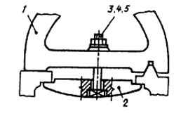
Figure 7.5 Figure 7.6
On assembly drawings, the following dimensions are applied:
1. Overall dimensions characterizing the three dimensions of the product. If one of the dimensions is variable due to the movement of the moving parts of the product, then the dimensions are indicated on the drawing at the extreme positions of the moving parts (Fig. 7.7).

Figure 7.7
2. Mounting dimensions indicating the relationship of parts in an assembly unit, for example, the distance between the axes of the shafts, mounting clearances, etc.
3. Installation dimensions that determine the dimensions of the elements on which the product is installed at the installation site or attached to another product, for example, the dimensions of the circles and diameters of the bolt holes, the distance between the axes of the foundation bolts, etc.
4. Operational dimensions that determine the calculated, design characteristic products, e.g. through hole diameters, thread sizes on connecting elements, etc.
5. The assembly drawings also indicate the dimensions of the holes for fasteners, if these holes are made during the assembly process.
6. All other parts of the assembly unit are numbered in accordance with the position numbers specified in the specification of this assembly unit.
7. Position numbers indicate on the shelves of leader lines drawn from points on the images of the components of the assembly unit, which are projected as visible on the main views or sections replacing them. Position numbers are placed parallel to the main inscription of the drawing outside the outline of the image and grouped into a column or line, if possible on the same line (Fig. 7.7, 7.8, a). It is allowed to make a common leader line with a vertical arrangement of positions (Fig. 7.8, b). As a rule, the position number is applied to the drawing once. The font size of the position numbers should be 1-2 sizes larger than the font size of the dimension numbers in this drawing.

Figure 7.8
In the process of assembling the product, some technological, so-called fitting, operations are performed. They are performed by joint processing of the parts to be joined or by fitting one part to another at the place of its installation. In these cases, assembly drawings make text entries similar to those shown in Fig. 7.9.

Figure 7.9
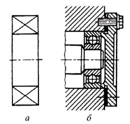
Many products have standard components. These include, for example, gland seals (Fig. 7.10). Their soft padding ensures the tightness of the holes through which the moving parts of the product pass. As a stuffing, hemp or linen fiber is used (Fig. 7.10, a, b) or a set of rings made of asbestos, leather, rubber (Fig. 7.10, c). The packing is pressed with a union nut (Fig. 7.10, a), a threaded sleeve (Fig. 7.10, b) or a stuffing box cover (Fig. 7.10, c). These parts are shown in the assembly drawings in the raised position.

Figure 7.10
Valves have standard mountings on stems or spindles. Fastenings can be carried out either by crimping the valve (Fig. 7.11, a), or by a wire clip (Fig. 7.11 b), or by a wire ring (Fig. 7.11, c). The spindle head can be mounted in the valve slot (Fig. 7.11, d).
Rolling bearings are standard products. They can be depicted on assembly drawings in a simplified way (Fig. 7.12, a) without specifying the type according to GOST 2.420-69 or, as shown in Fig. 7.12, b, - with the image of rings and balls or rollers.

Figure 7.11